Chassis
The chassis of the tripeds connects all three legs and is made up of 3 layers as well as a battery bay. An overview of the chassis and the names of each layer can be seen below
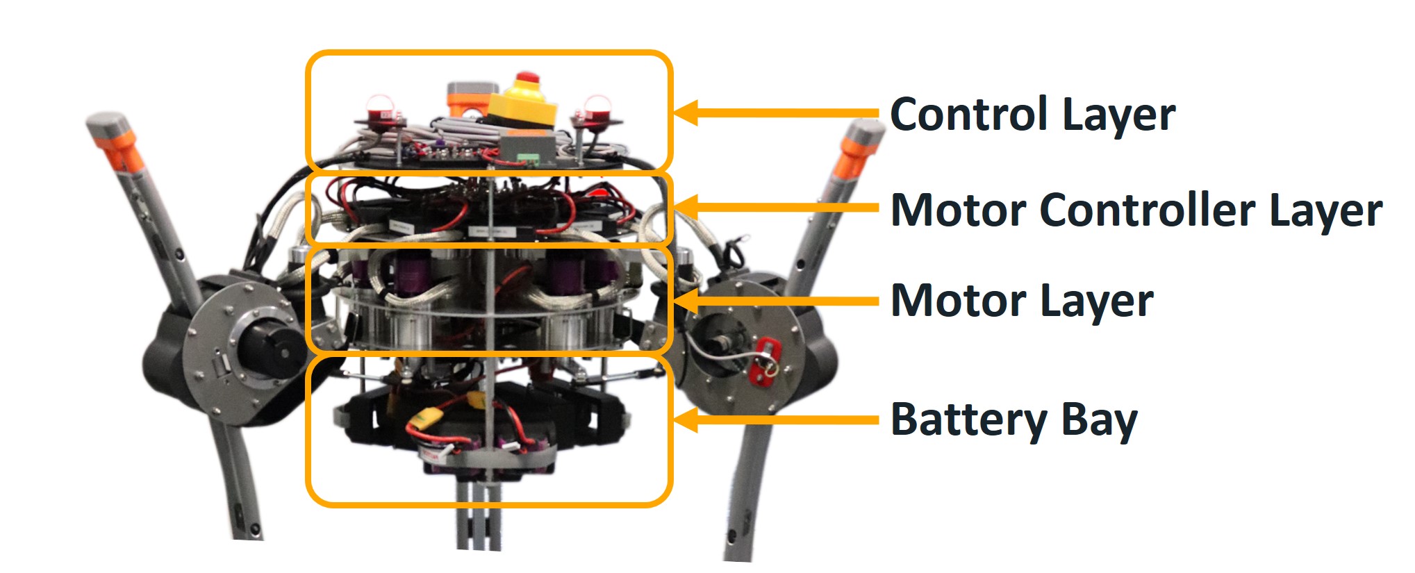
Control Layer
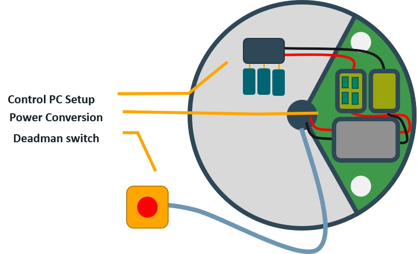
The first layer houses the control pc of the system, powered by a power converter and secured using a fuse box.
The Top Layer also features two round RGB status LED which communicate the state of the System. Additionally, a deadman switch is accesible which is connected via a 3 meter long cable and is capable of instantly shutting of power to the motor controllers.
Motor Controller Layer
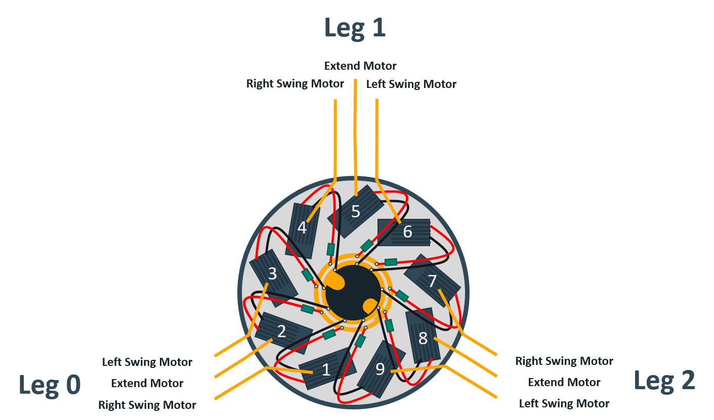
The motor controller layer houses, as the name might imply, the Hacker Hercules m50 motorcontrollers controlling the torque of each of the 9 motors of the system. The image above shows the mapping of motor controllers onto the controlled joints.
Motor Layer
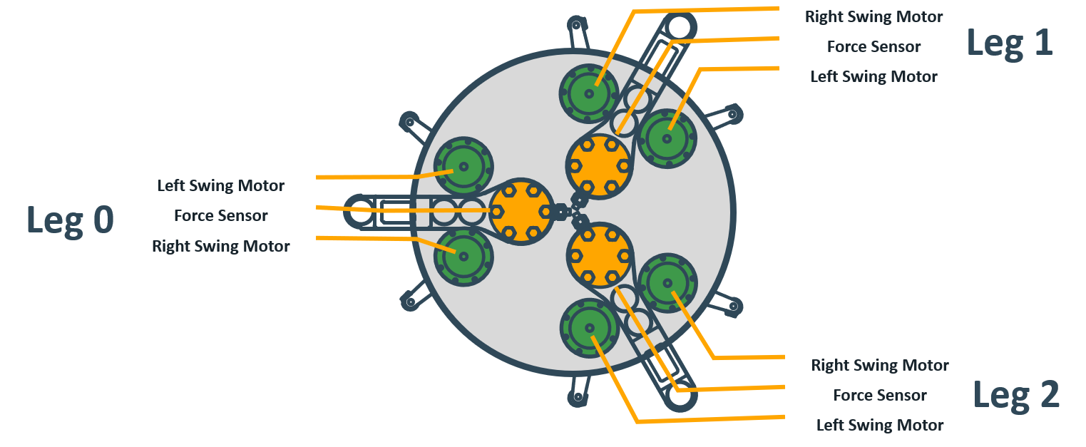
The Motor Layer connects the chassis to each sub-robot. This connection consists of a aluminum bridge that rests upon the 6DOF force sensor, as well as the two output lever connecting the swing motor to the closed chain used to control the leg orientation. More information can be found in Legs.
Battery Bay
The battery bay houses the six batteries used to power the system.
They are distributed into 3 parallel connected pairs of serially connected batteries. To prevent equalizing currents between these pairs, they should always be at the same charging level.
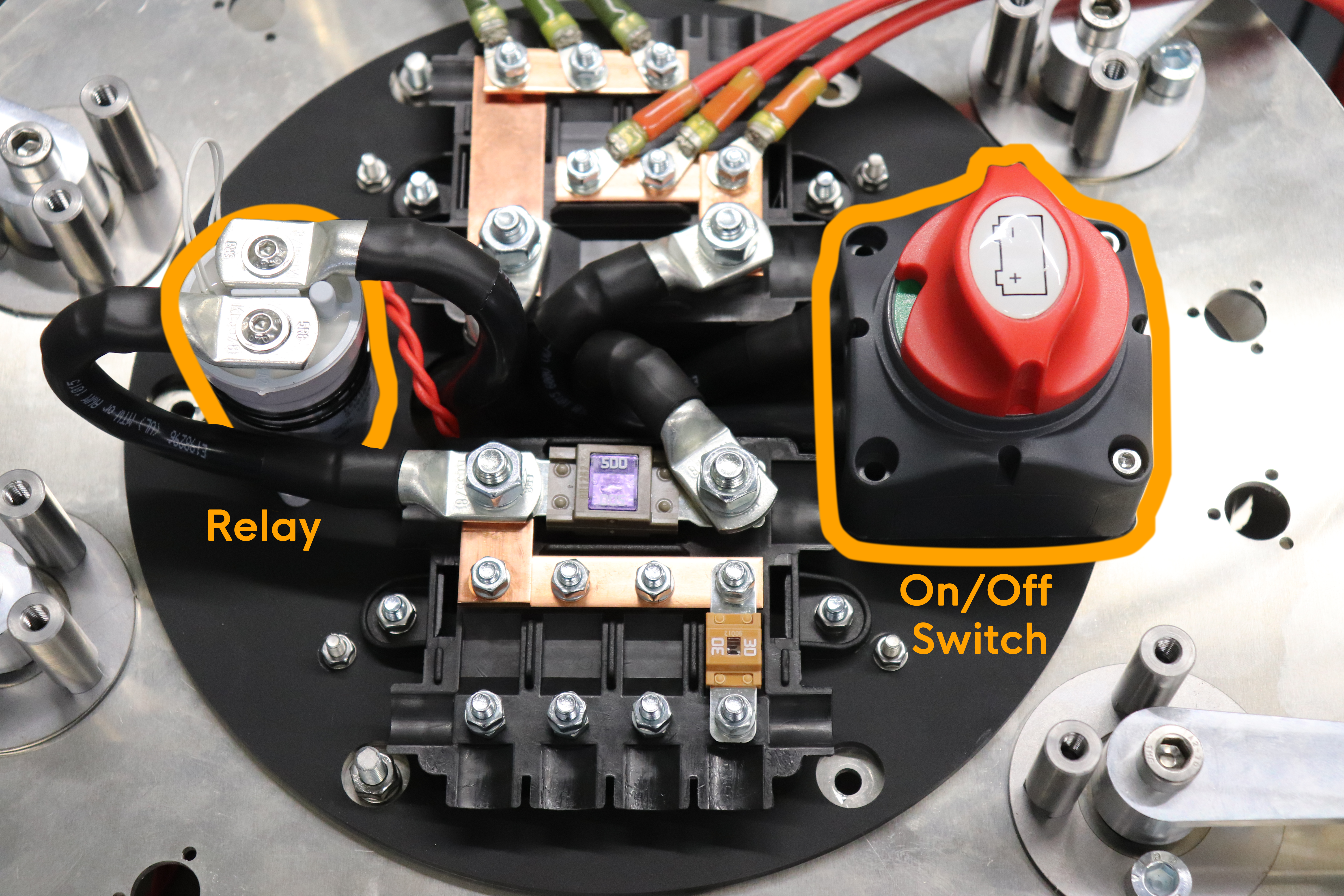
The batteries are connected to an on-off switch of the system as well as a relay, which are shown down below.
The red button shown implements the on-off switch and has to be turned 90 degrees to switch on the System.
The relay is connected to the hardware safety switch located on the control layer. Disengaging the relay stops current from flowing into the motor controller layer.