Kinematic Model
This section offers a short overview of the kinematics as well as important coordinate systems of the TriPed.
It assumes that one is already familiar with robotic kinematics and the general terminology. If this is not the case, this page offers a short tutorial.
A full specification of the TriPeds transformations can be downloaded below.
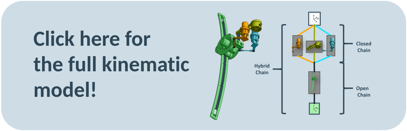
Kinematic Structure of a Leg
Each leg is a so called hybrid chain whose kinematic structure is pictured below.
The different colors of the figure aim to highlight the multiple different transformations that lead to the same coordinate system.
Since the three colored parts at the top all lead to the leg linear part of the leg, they form a closed chain, while the leg linear part itself is an open chain.\
The hybrid nature (specifically the closed subchain) of the system has many repercussions in terms of th kinematic calculations as well as available control strategies.
These are discussed in the last section.
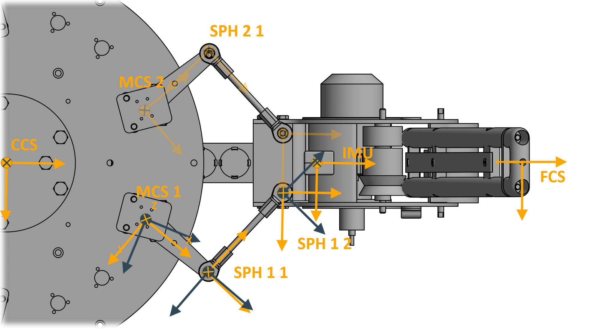
Coordinate Frames
This sections provdes conventions and standarts for the robots coordinate frames. Note that the TriPed does not use the popular Denavit Hartenberg Conventions as these arenot suited for closed kinematic chains. The Coordinate Frames of the TriPed instead adhere to the following conventions:
- Each frame is represented by a right-handed coordinate system
- the orientation of this coordinate system is specified using quaternions
- https://de.wikipedia.org/wiki/Quaternion
- The transformations between connected Frames is defines through a homogeneous transformation Aoldnew
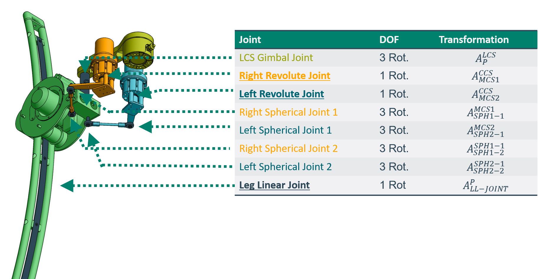
Meanwhile the transformations of joints adopt the following conventions:
- Each joint is specified by a base and a follower frame
- The base frame is located at the position of the joint.
- The transformation between base and follower frame is performed by the joint
- Joints with single degrees of freedom actuate around the Z axis.
The resulting frames and their naming conventions can be seen down below.
A blue frame represents a base frame and a orange frame a follower frame.
The full specifications of all Transformations can be found by clicking on the image below:
Closure Equation
Aranging all connected transformations into a graph as seen below, one can identify the closed kinematic chain of the robot between the ccs frame and the p frame. Traditional kinematics such as discussed in the tutorial however deal only with the computation of open chains between the two frames.
For a closed chain with unactuated joints on has to additionally enforce that all paths (in this case three) converge on the same frame. This is done via the so called closure equation.
For more details about how a closure equation is formulated and used to solve the kinematics of a root see the triped kinematics tutorial
Dealing with multiple solutions
The solution of the closure equation is not unambiguous as can be seen down below.
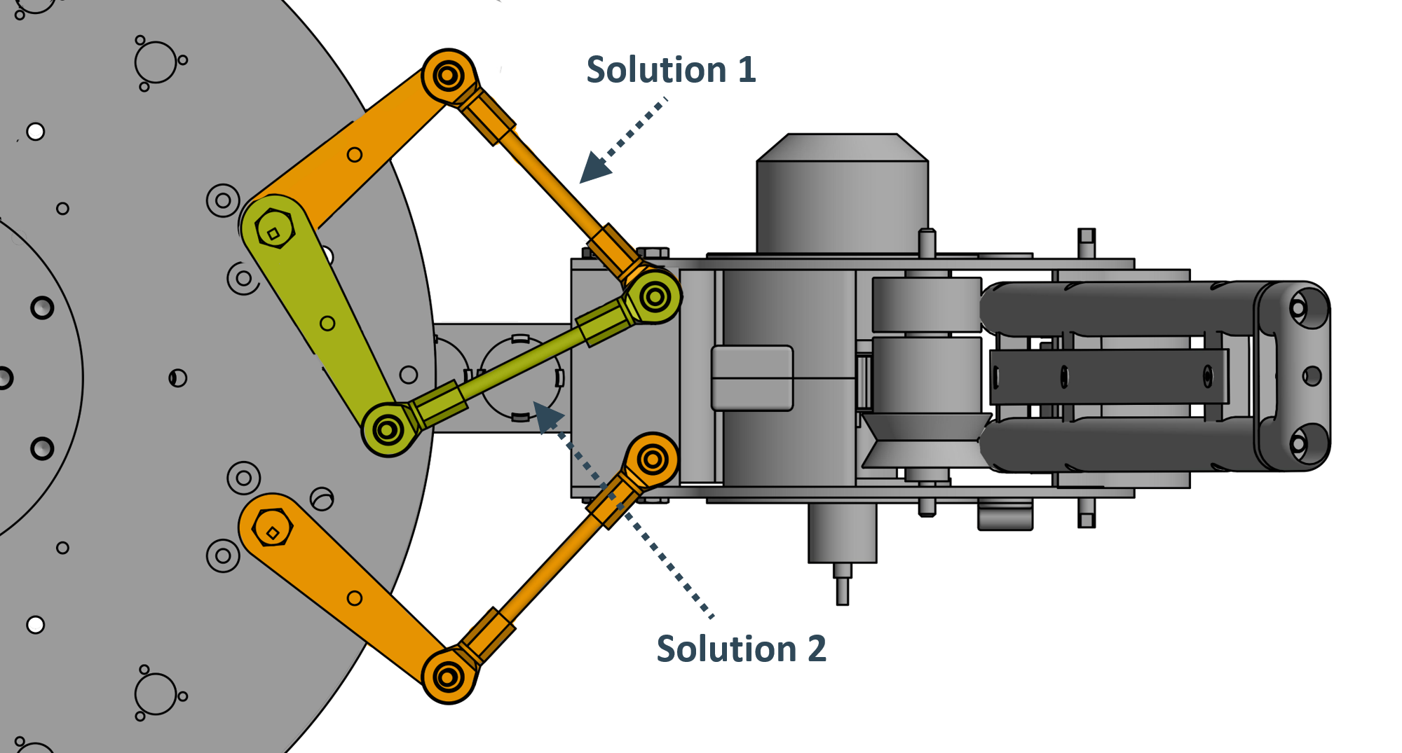 To prevent the system from jumping between solution, one can either give the solver the last computed joint state as a initial guess or penalize solutions that have the motor pointing inward since these are intrinsically more unstable (see Legs for more details).