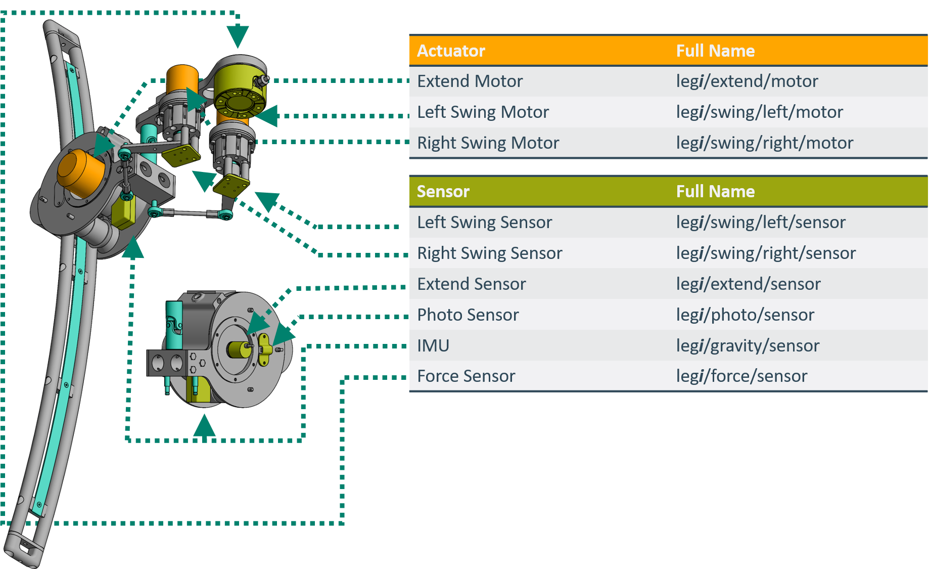
One Legged Subrobot
Each Leg of the TriPed hase 3 degrees of freedom allowing the control of the legs pitch and roll as well as its length. The length of the leg is controlled by the so called extend motor which moves the rounded leg upwards and downwards using a belt. The angle is controlled by two motors located on the chassis which move the hip of the robot (called drive module) via two coupling rods. This is further explained in Triped Kinematics.
The full structure of the legs can be seen in the figure below.
It shows all joints in turquoise, as well as all the motors and sensors, pictured in orange and green respectively.
Note that the motors and force sensors on the right hand sight are normally connected to the chassis.
The next sections will go into more detail about how the robot is actuated. A full overview of the kinematics of each joint can be found in Triped Kinematics.
Swing Joints
The two swing joints allow the leg to swing, providing two rotational degrees of freedom. Since there are two of them for each leg these motors will be called the left/right swing joint of the i-th leg. Where left and right is determined when standing in front of the leg and looking at the robot and i again denotes the leg number.
Swing Motor
The two smaller Motors are called swing motors.
In the full system the swing motors are affixed to the chassis and control the angle of the system using a closed chain for more information see TriPed Kinematics).
Since the motors need to supply a lot of torque to the system a harmonic gear with a gear reduction of 1:50 is used to actuate the mechanism.
This gearbox results in low coupling between the forces of both motors.
The full system can be seen in the figure below
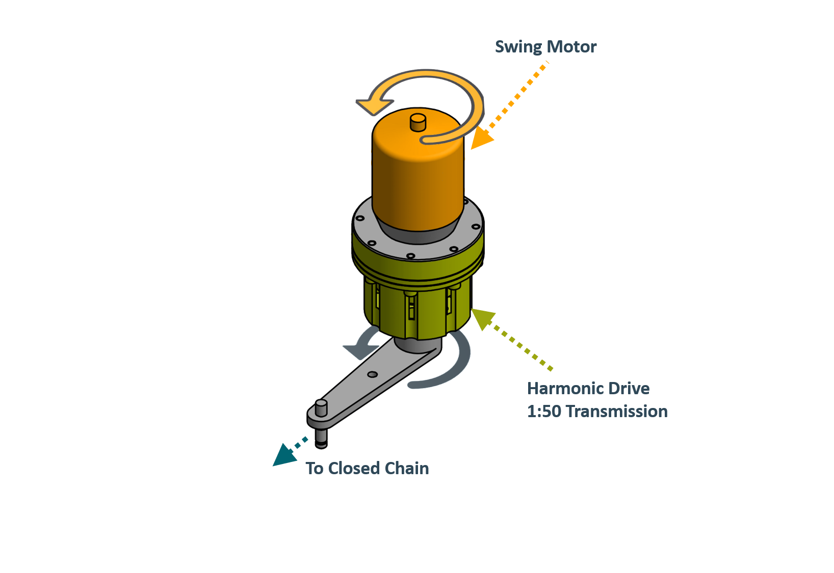 The TriPed uses Hacker A50 Brushless Motors for the swing motors and CPL-20A-50-2A harmonic drives for the gear conversion.
These harmonic drives necessitate a motor speed limit of 6500 rpm.
The TriPed uses Hacker A50 Brushless Motors for the swing motors and CPL-20A-50-2A harmonic drives for the gear conversion.
These harmonic drives necessitate a motor speed limit of 6500 rpm.
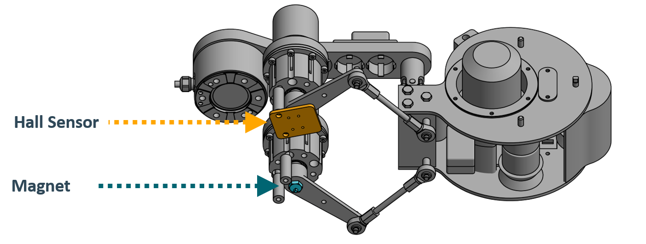
Swing Sensor
The left and right swing senso}, measure the position of the output of the harmonic drive of each swing motor.
They are implemented using As5047D Hall Sensors as well as magnets attached to the output lever of the Gear (see figure
Joint Range
The Jointrange describes not only the available range of movement but also the conventions for a angle of zero,
While the joints can theoretically swing in 360° degrees they are bounded by not only the closed kinematic chain but also two stoppers at each side of the motor shaft.
These constraints can be seen in the following graphics
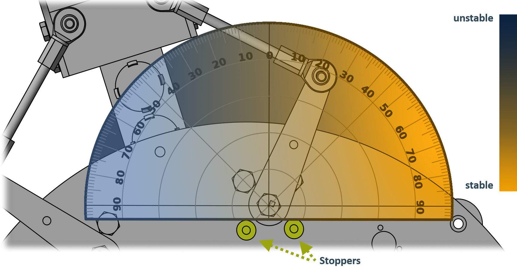 It should be noted that the actual robot measures all angles in radians not degrees.
The progression from orange to blue is meant to visualize the stability constraints provided by the kinematic chains as the system goes from positive angles (orange) to negative angles (blue).
Roughly speaking this means that while the system is capable to operate at the full range, the motor shouldn’t go into this range since the system tends to become unstable.
This is however only a simplification as the system can also become unstable in different konfigurations based on the state of the other motor. This is discussed in Triped Kinematics.
It should be noted that the actual robot measures all angles in radians not degrees.
The progression from orange to blue is meant to visualize the stability constraints provided by the kinematic chains as the system goes from positive angles (orange) to negative angles (blue).
Roughly speaking this means that while the system is capable to operate at the full range, the motor shouldn’t go into this range since the system tends to become unstable.
This is however only a simplification as the system can also become unstable in different konfigurations based on the state of the other motor. This is discussed in Triped Kinematics.
Extend Joint
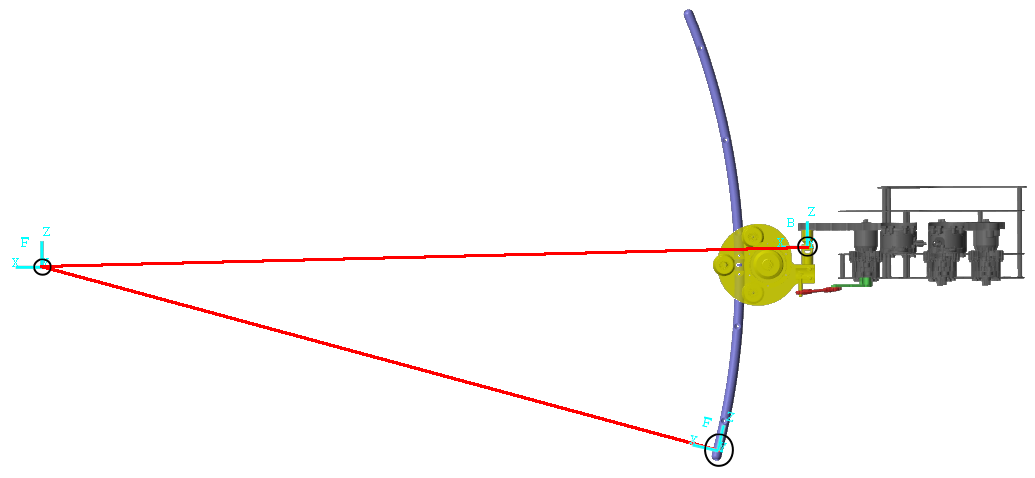
As the name Implies the Extend Joint is responsible for the extension and retraction of the curved leg. contrary to the swing joint, this joint is virtual, meaning that no phyiscal part corresponds to it. Instead it is located at the point around which the curved part of the leg rotates. This can be seen in the figure below
Extend Motor
The extend motor moves the extend joint using a flexible tooth belt attached to the leg. The toothbelt on the curved leg can in this case be viewed as a kind of giant gear attached to extend joint which is moved by the motorshaft afixed to the extend motor.
This creates a gear reduction of 0.07/(2pi1.5).
This system can be seen in the figure below
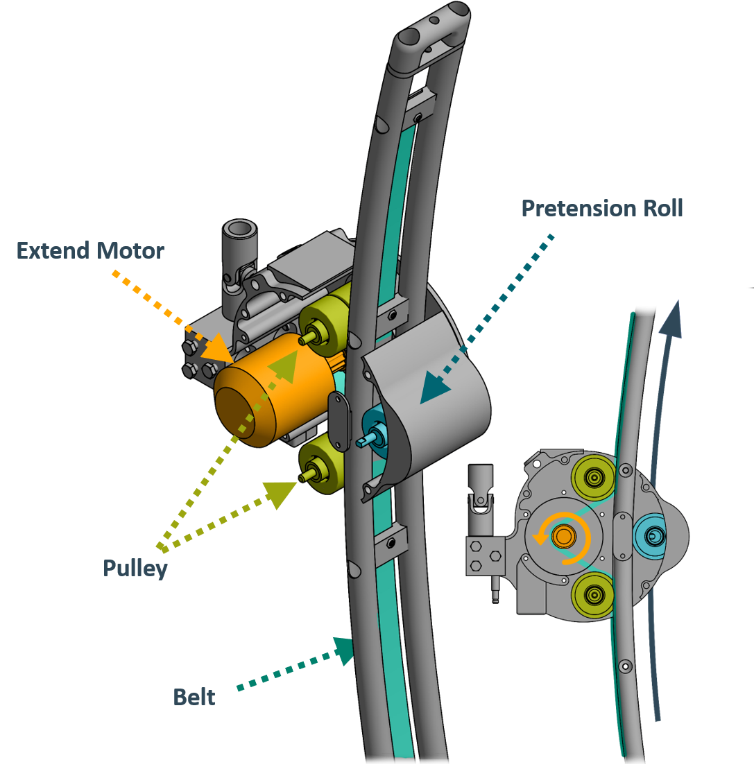 Note that this means that the motor turns in the opposite direction of the leg!
The specific model of the extend motor is a Flipsky BLDC Belt Motor 6374 190KV 3250W Electric Skateboard Motor capable of applying 8Nm of torque to the leg.
Note that this means that the motor turns in the opposite direction of the leg!
The specific model of the extend motor is a Flipsky BLDC Belt Motor 6374 190KV 3250W Electric Skateboard Motor capable of applying 8Nm of torque to the leg.
Together with the gear reduction this gives each sub-robot enough torque to temporarily support more than double (80 kg) the weight of the system (30 kg). The tension of the belt can be adjusted using the pretension roll pictured in the figure above. Since each sub-robot has it’s own extend motor, a given extend motor is called extend motor of the i-th leg where i denotes the leg number.
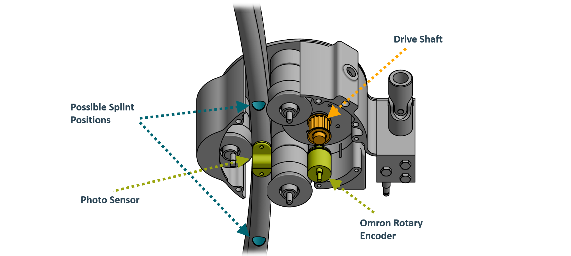
Extend Sensor
The extend sensor measures the position of the extend motor using a Omron E6A2-CW5C 500 P/R Rotary Encoder.
Therefore the gear reduction of 0.07/(2pi1.5) has to be applied to get the correct angle.
Since this rotary encoder measures only relative position, the system includes a photo sensor, that measures the position of a splint inside the leg linear part.
This enables the conversion from a relative position to an absolute position.
The full setup can be seen in the figure below:
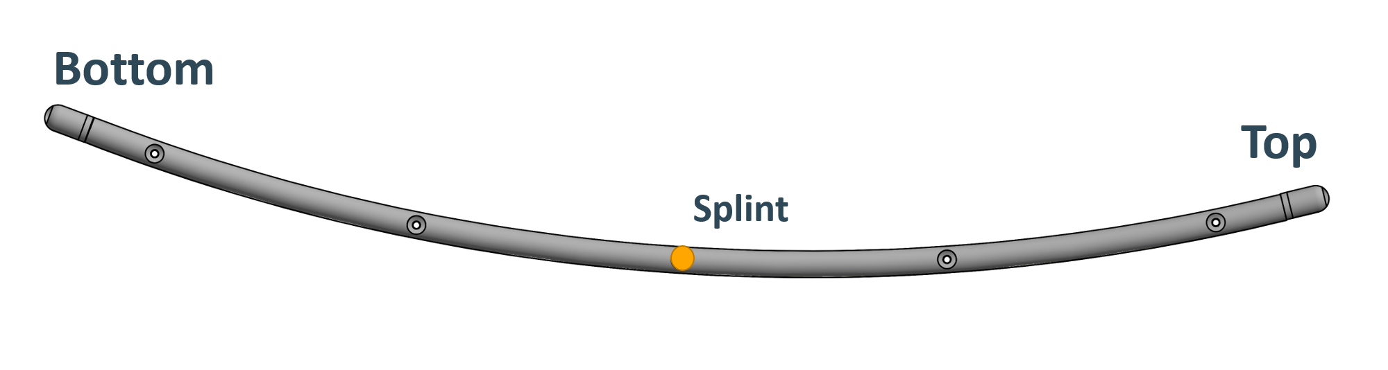
 The Splint that triggers the Photo sensor can be inserted in multiple possible positions along the leg.
Its default position is indicated in the figure below and corresponds to a extend joint angle of pi/10.
The Splint that triggers the Photo sensor can be inserted in multiple possible positions along the leg.
Its default position is indicated in the figure below and corresponds to a extend joint angle of pi/10.
Joint Range
The range of the Joint defines zero as the position in which the leg is fully retracted, while the value of the fully extended leg is 0.489 rad.
IMU
The TriPed uses a BMA280 Digital, triaxial acceleration sensor to calibrate the motors on startup by providing a known leg orientation and thereby motor position.
Force Sensors
The 6 Degree of Freedom force sensor are connected to the bridge on which the leg assembly is mounted. This enables the system to measure the load on each sub-robot.
It should be noted that these sensors are currently not built into the system.
This is because optimal working point for the sensors still has to be determined. If it is chosen to low the strain gauges inside the sensors, which are extremely delicate, could snap during an unforeseen movement. If it is chosen too high, the sensors would not be able to produce high-resolution data.
For this reason, it was decided to only integrate them once a dynamic model of the legs is found from which an operating point can be specified.
In the meantime, the bridge is connected to the chassis using aluminum blocks of the same size.