About the Matlab Simulation
The Matlab simulation offers a full library of all assembly pieces of the TriPed. Its goal is to aid in the design of walking experiments for the robot but also to help teach people about robotics and robotics simulation.
For this purpose, the simulation is completely open-source to allow robotics enthusiasts to play around with it. It also comes with several demonstrations and tutorials to help people understand how to program and develop a real robot.
You can download the simulation by clicking on the image below:
To learn how to use the library visit getting started
Overview
the library is divided into four 4 directories called Full Model, Simplified Model, Environment, Kinematic Utils
Full Model
This directory contains the assembly pieces of the TriPed. These form a hierarchy with ever more complicated pieces. This hierarchy is pictured down below:
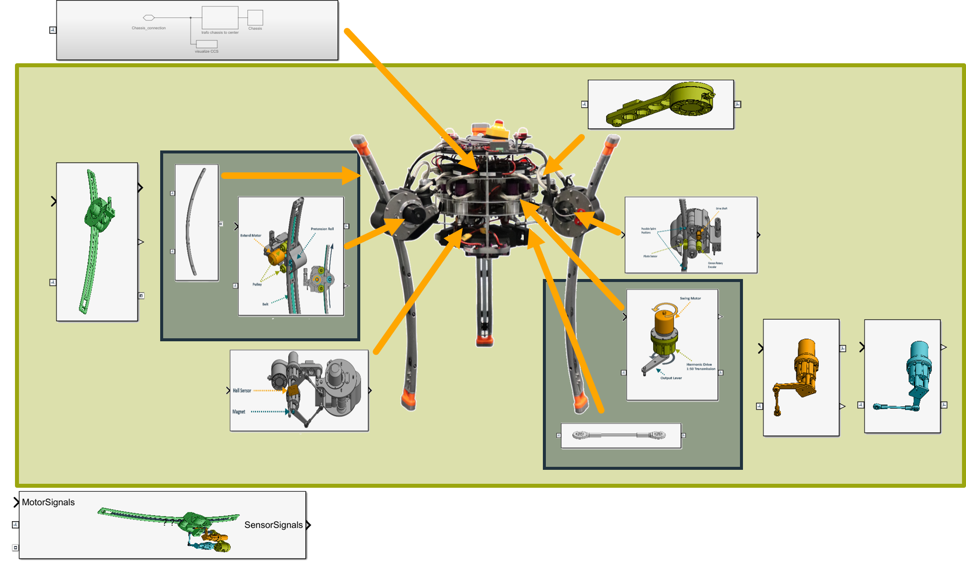
These can then be used to construct the full model of the TriPed which is also contained in the simulation. The TriPed is in this case made up of three legs and a central chassis.
Each leg can be further subdivided according to its kinematic subchains. These subchains then house their actuators. The sensor modeling however is done separately at the TriPed model layer to allow people to use the subparts without the noise that the sensor models introduce.
Conventions for Actuators and Sensors
Since the simulation is meant to be used to develop algorithms for the real robot, it must follow the conventions laid out on legs. However although the actuators are controlled via torque the simulation uses motion control for each joint, which means that one can directly specify the position of each joint. This is done because in terms of architecture the simulation provides the same interfaces as the joint level control layer discussed in the embedded architecture.
For this reason, the full model also supplies ROS communication bridges which allow the direct testing of robot software on the simulation. These offer ROS topics with the same naming scheme as the real joint level control package.
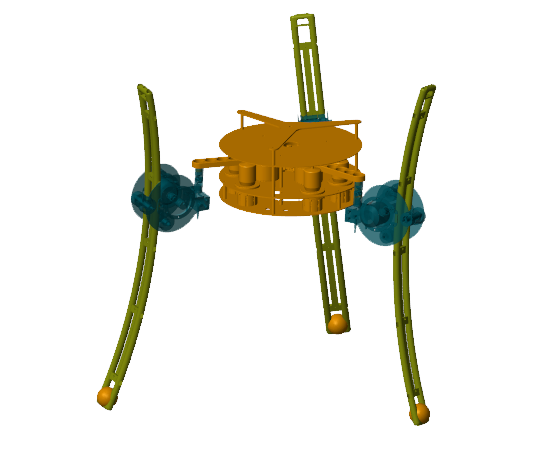
Simplified Model
While accurate, the full model has two distinct disadvantages:
- It is “slow” when actuated with a kinematic model
- Its hybrid chain makes it unusable for most robotic toolboxes
The first disadvantage makes it difficult to perform fast walking experiments, which is especially detrimental when trying to train a reinforcement learning model. The second disadvantage makes it harder for students to apply the tools they learned since hybrid chains kinematic calculations are seldomly taught in robotics courses or included in robotics tools.
For this reason, two simplified models are provided.
Instead of actuating the swing motors, that inevitably control the position of the gimbal joint (For reference see Kinematic Model), both directly actuate the gimbal joint.
This eliminates the closed chain from each leg.
Additionally one of the two models allows direct setting of foot position by already using a forward and inverse kinematic model.
To keep the range of motion between this simplified simulation and the full model, the range of motion of the gimbal joint must be constrained. The pitch and yaw are constrained to +-0.523599 rad as this is the effective working space of the full model (while the full model can move further the mechanism becomes unstable). Accordingly, a maximum angular velocity and acceleration were calculated from the maximum velocity of the swing joints.
However, the role of the joint is normally determined by the pitch and yaw through the closed chain. To preserve this dependency the simplified kinematics shown in the last section constrain the yaw. When using the simplified model with direct joint control, however, this dependency has to be preserved by hand.
Environment
The environment directory deals with the simulation of environments the TriPed can traverse. For this purpose, a variant subsystem block was provided witch allows the TriPed to either walk around in the world or be fixed in place for debugging purposes.
Additionally, different ground configurations are provided which aim to simulate different walking surfaces for the robot.
Ground Contact Modeling
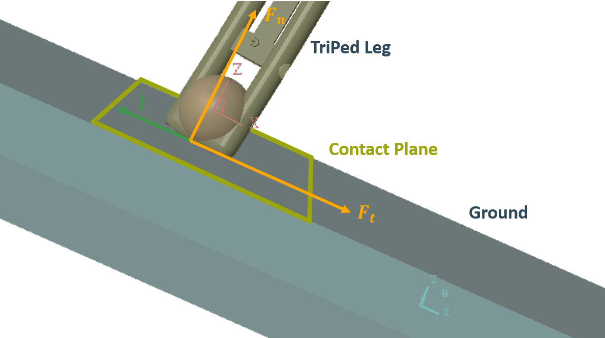
Ground contact can be decomposed into two components:
- A normal force Fn
- A tangential friction force F_t These are defined in terms of the contact plane between ground and foot as can be seen down below: The normal force is modeled using a dampened harmonic oscillator with parameters mass, stiffness, and dampening. While the mass is dependent on the weight of the robot, stiffness, and dampening represent the force transmission between foot and ground.
In the case of the TriPed, the stiffness and dampening are not only dependent on the configuration on the ground but also the dynamics of the leg, which in the case of the TriPed means the dynamics of the extend motor. These are tuned to allow smooth foot stepping and therefore dominate the stiffness and dampening on the ground. For this reason, all grounds have the same stiffness and dampening to approximate the behavior of the extend motor.
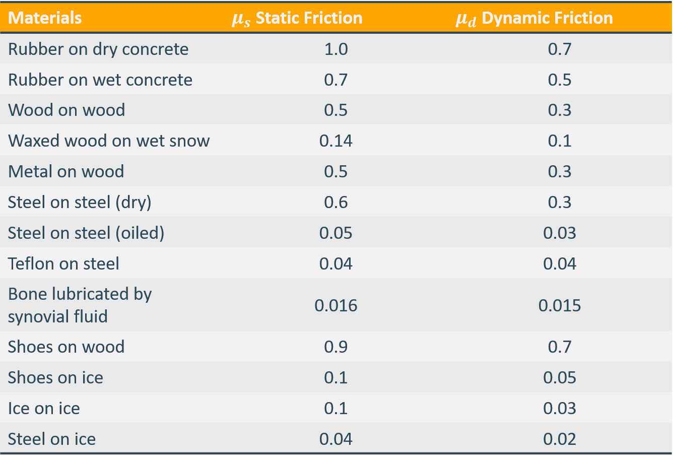
For the tangential force, coulomb friction with stiction is used. These offer two coefficients of friction.
A table of different friction coefficients based on the material of the ground and the foot can be seen below.
Kinematic Utils
The kinematic utils directory contains basic kinematic models for the system to be able to directly specify the foot position in task space.
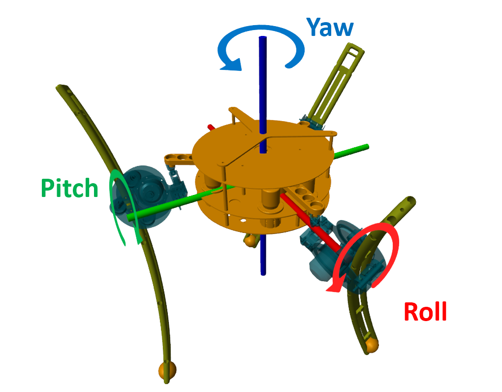
Additionally, the utilities provide a full-body kinematic block, which allows not only the specification of foot positions but also the roll, pitch, and yaw of the TriPed chassis as shown in the figure below:
 It should be noted that the kinematic calculations and model are rather basic, a much faster and more precise solution is included in the TriP kinematic libray.